![]()
Mast with tilted SPA-2-sensor and USH-9
Follow the steps below to set up the mast. It is recommended to attach all required items while the mast is lying on the ground. In this way no ladder or step is needed.
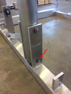
- Remove the bolts of the mast bracket on cross-profile nr. 11 and slide the bottom end of the mast into the bracket.
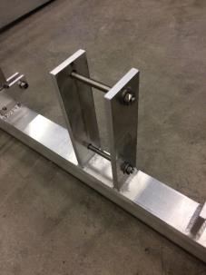
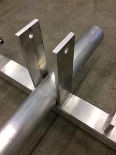
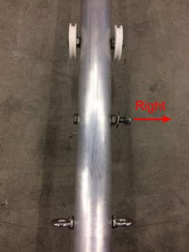
- Turn the mast so that the protruding end of the attached bolt is facing to the right.
- Fix the mast with the upper bolt of the mast bracket on cross-profile nr. 11.
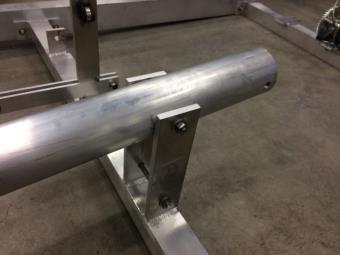
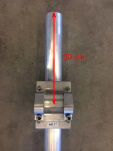
- Slide the bracket for the cross-arm approx. 30 cm over the top of the mast and tighten it loosely.
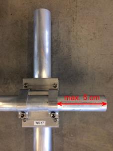
- Slide the cross-arm into the bracket so that the short end protrudes max. 5 cm and tighten it. Make sure that the cross-arm is pointing perpendicular to the length of the supporting frame when it is standing upright! Now, tighten the 4 bolts of the bracket embracing the mast.
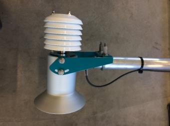
- Mount the USH-9 with its bracket to the cross-arm. Make sure that the USH-9 is pointing towards the ground and that it is parallel to the mast when erected.
ATTENTION The tilt of the USH-9 sensor should be less than ±6° off the vertical axis!
- Plug the sensor cable to the USH-9 and fix it along the cross-arm and mast with cable ties. Coil up the excess sensor cable and attach it to the mast to avoid damage during the remaining installation steps.
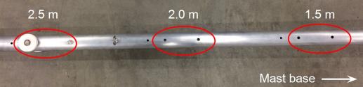
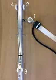
- Verify that the pulleys attached to the mast match the mounting position of cross-profile nr. 8. The default position is 2.5 m (see next figure).
ATTENTION The pulleys on the mast can be mounted in three different positions, depending on the expected snow height. As illustrated in the figure below, the available positions are 1.5, 2.0 and 2.5 m. The selected position must match the mounting position of cross-profile nr. 8 described in the previous section.
- Attach the loop of cable nr. 23 (labelled 3) to the bolt below the pulley of the mast as shown in the next figure.
- Attach pulley nr. 15 to the ring nut of the tilted SPA-ribbon-sensor. Run cable nr. 23 between the pulley and the ring nut. Make sure to attach the pulley to the ribbon end with the cable output and in the position shown in the figure below!
- Fasten the other end of cable nr. 23 to the second pulley as shown in the figure below.
- Run the cable nr. 23 through the second pulley as shown below.
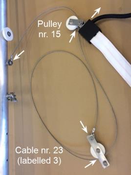
- Fix cable nr. 23 with a cable tie to the mast as shown below. Make sure to run the cable around the pulleys exactly as shown in the figure. Only then the hoist to tighten the SPA ribbon sensor will work properly.

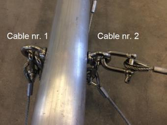
- Attach the guy cables nr. 21 (labelled 1) with the shackles to the ring nut on the left side of the mast.
- Attach the guy cables nr. 22 (labelled 2) with the shackles to the ring nut on the right side of the mast.
- Push up the mast into its upright position and fix it with the second bolt on cross-profile nr. 1
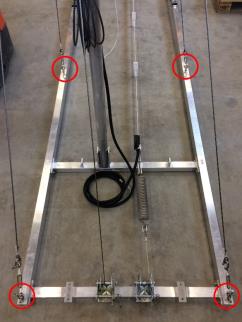
- Secure the mast with the four guy cables to the base frame. The turnbuckles of cables nr. 21 (labelled 1) are mounted to the ring nuts on base-profile nr. 2 (left), and the buckles of cables nr. 22 (labelled 2) to the ring nuts on base-profile nr. 1 (right).
ATTENTION Tighten the four guys equally! The mast must point exactly upright for proper operation of the snow level sensor!