![]()
DIP-switches
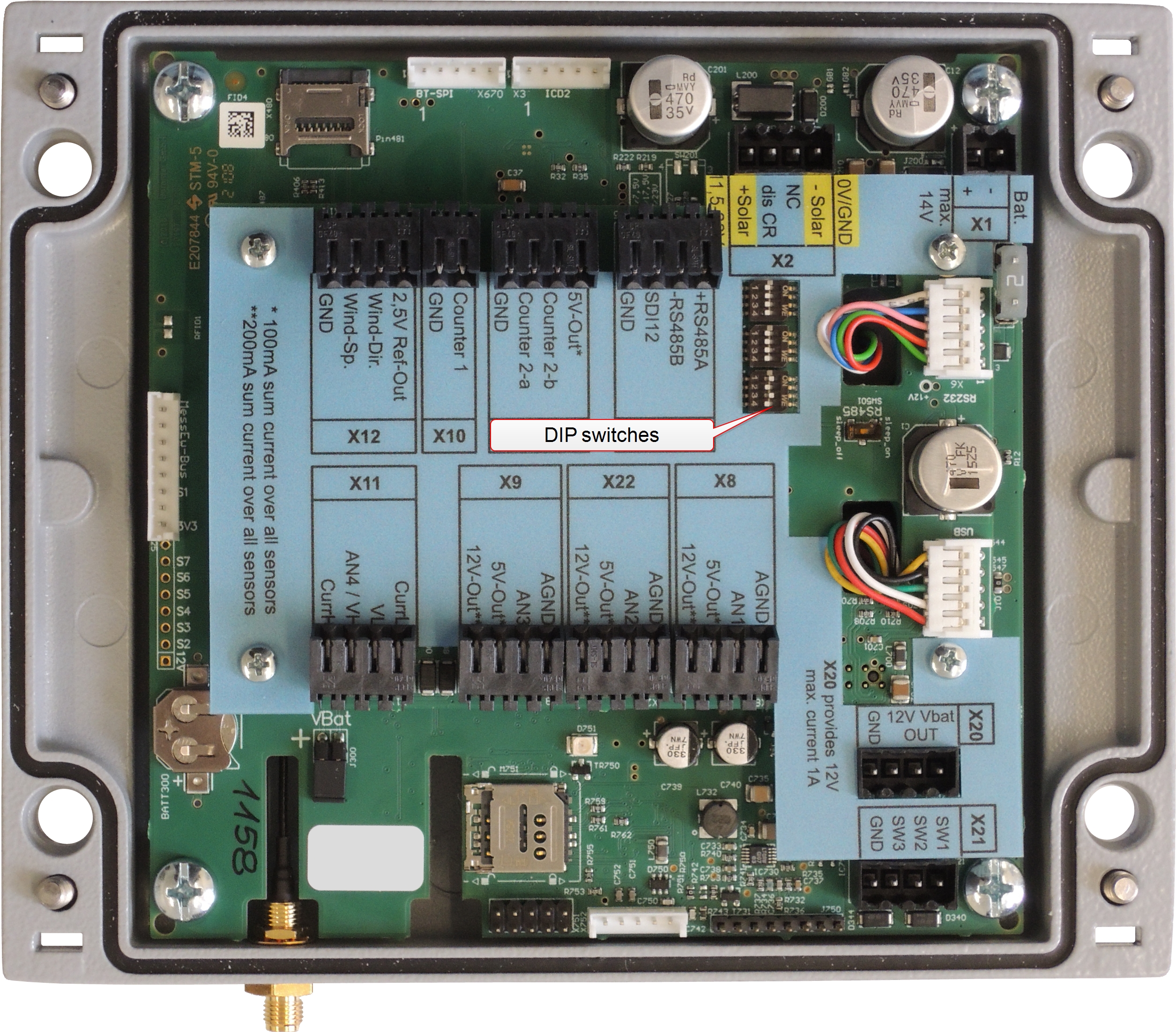
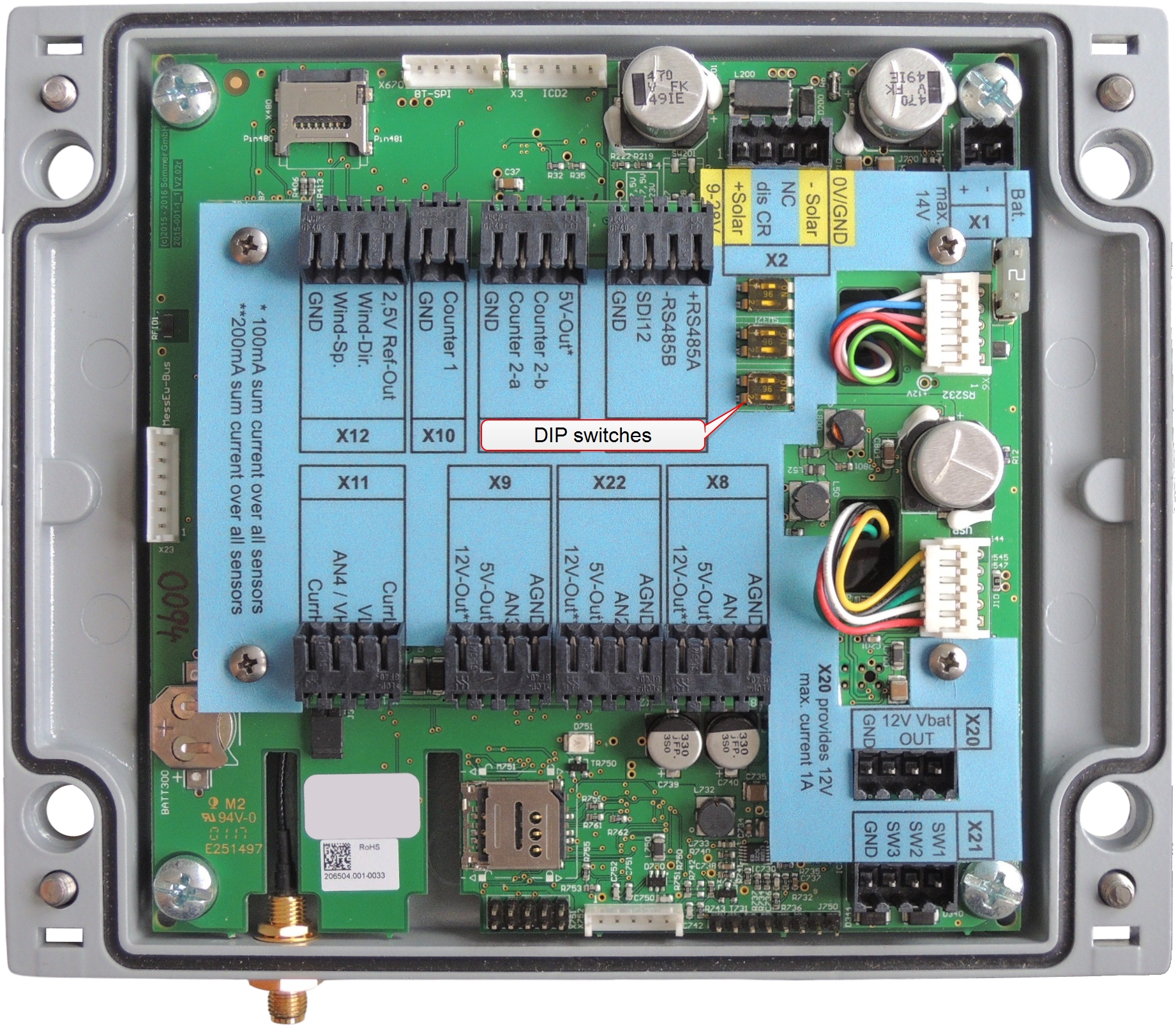
The signal type of the counter inputs can be configured with three DIP-switches. Their location is shown in and .
To configure the counter inputs to receive signals from a sensor with either an open collector output or a source output, set the DIP-switches according to the following table:
New MRL-7 versions (3x4 switches)
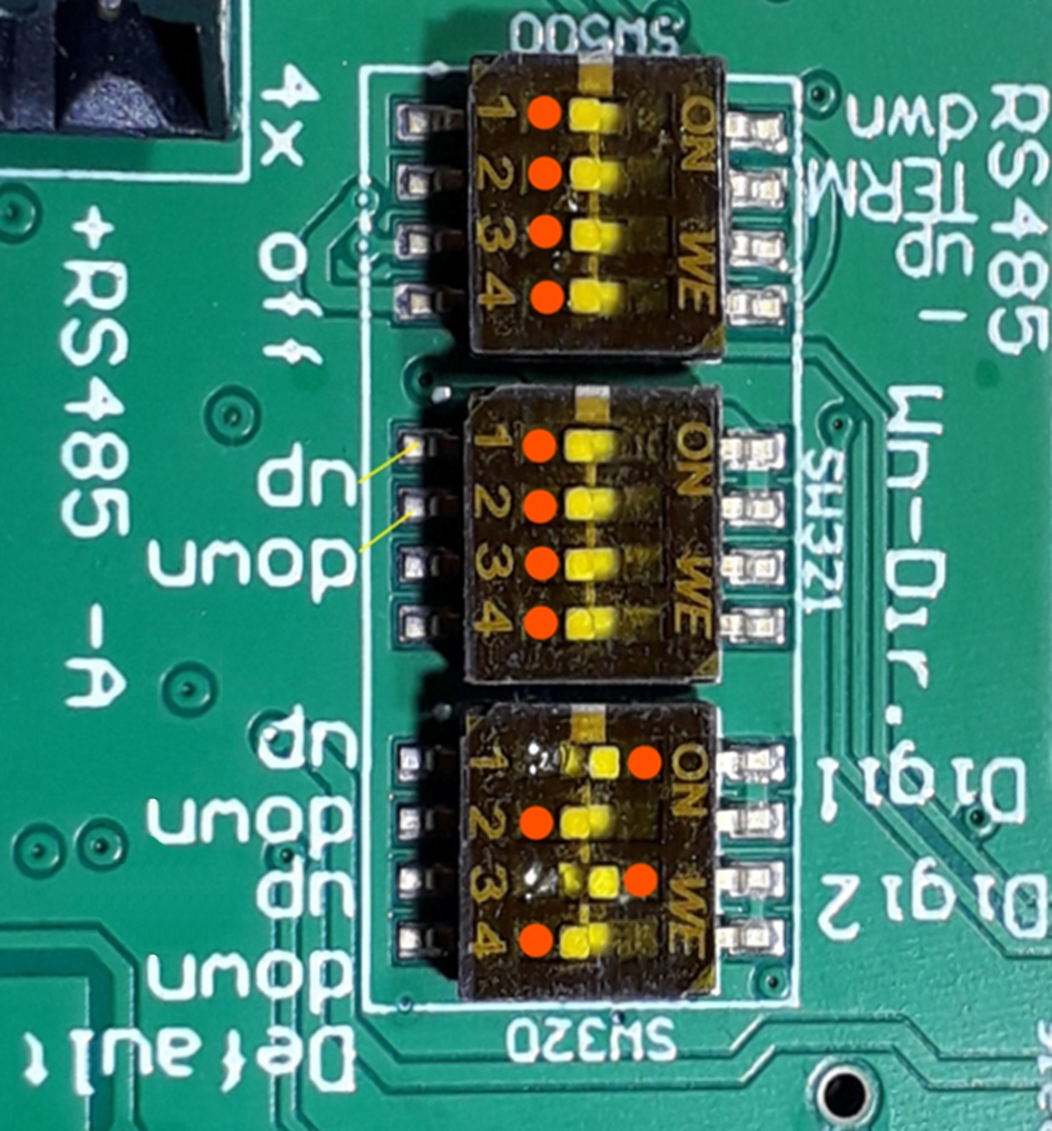
Orange dots show the default positions. |
|
- Input-Areas of digital channels
-
pull-down: 0 ... 0,6 V pull-up: 2 ... 28 V - Usage of Wn-Dir
-
Wind-direction: SW1 and SW2 to Off Counter 2-b: SW1 to On, SW2 to Off Trigger: SW1 to Off, SW2 to On - Usage of Digi
-
Counter 1 & 2-a: SW1 to On, SW2 to Off, SW3 to On, SW4 to Off Trigger 1 & 2: SW1 to Off, SW2 to On, SW3 to Off, SW4 to On
Old MRL-7 versions (3x2 switches)
|
DIP-switch |
Position |
Function |
|---|---|---|
|
SW322 |
(Default) |
Pin Wind-Dir on terminal X12 is configured as analog input to receive a wind direction signal (potentiometer), and pin Counter-2b on terminal X19 is deactivated. |
|
|
Pin Counter-2b on terminal X19 is configured as counter input with a pull-up resistor (connects to a sensor with an open-collector output). Pin Wind-Dir on terminal X12 is deactivated. |
|
|
|
Pin Counter-2b on terminal X19 is configured as counter input with a pull-down resistor (connects to a sensor with an active output). |
|
|
SW321 |
(Default) |
Pin Counter-2a on terminal X19 is configured as counter input with a pull-up resistor (connects to a sensor with an open-collector output). |
|
|
Pin Counter-2a on terminal X19 is configured as counter input with a pull-down resistor (connects to a sensor with an active output). |
|
|
SW320 |
(Default) |
Pin Counter-1 on terminal X10 is configured as counter input with a pull-up resistor (connects to a sensor with an open-collector output). |
|
|
Pin Counter-1 on terminal X10 is configured as counter input with a pull-down resistor (connects to a sensor with an active output). |


